L-127 Delayed LFO module for Eurorack / Doepfer A100 system.
From the top down:
Gate/Trigger in jack + LED
Rate knob + LED
Delay knob + LED
Initial Phase/Rise Time/Count knob + LED
Bank Selection and Mode button + LEDs (short press = bank selection 1-2-3, long press = Delayed/Rise Time/Counting mode)
Wave Selection knob + LED
Output jack + polarity LEDs
The L-127 is an LFO with advanced trigger synchronization and delay options. The LFO rate is set by a knob. The Rate LED blinks on and off for rates above approx. 1Hz, and fades on and off for rates under 1Hz.
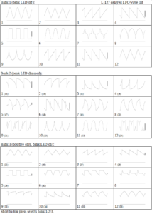
There are three banks of waveshapes (1-2-3), switched by short press of mode button (LED off/dimmed/on = bank 1/2/3). Each bank contains 12 waveshapes (= 36 waveshapes total). The waves in the last bank (LED on) are unipolar (positive voltages only). Mode and bank is memorized.
There are three modes of operation: Delayed (DL; also known as Initial Phase), Rise Time (RT), and Counting (C). The mode is switched with a long press of the Mode button. The PHase/RiseTime/Count knob operates differently depending on the selected mode:
INITIAL PHASE: An incoming gate or trigger causes the LFO to immediately jump to zero (normally 0V output; may be set with an internal trimmer), and it stays at zero for the time set by Delay (maximum delay = 8 seconds). After the Delay period, the LFO starts playing back the chosen waveform, with an initial phase (position in the wave) set by the PH knob.
RISE TIME: An incoming gate or trigger causes the LFO to immediately jump to zero, and it stays at zero for the time set by Delay (maximum delay = 8 seconds). After the Delay period, the LFO’s output rises in level at a rate set by the RT knob (maximum rise time = 8 seconds) until it reaches full amplitude.
COUNTING: In this mode, the L-127 works as a one-shot transient or modulation generator, rather than as a normal LFO. Middle and bottom jumpers on the back of the PCB determine how this mode behaves.
There are two submodes for counting, set by the middle jumper on the PCB:
– Jumper removed (“delay first”): An incoming gate or trigger causes the L-127’s output to immediately jump to zero, and it stays at zero for the time set by Delay (maximum delay = 8 seconds). It then plays back the selected wave for the number of periods set by the C knob (from 1 to 16). When all of the cycles are finished, the L-127 then waits at zero until the next gate or trigger
– Jumper set (“delay between”): An incoming gate or trigger causes the L-127’s output to immediately play one cycle of the chosen waveform. It then pauses at zero for the time set by the Delay knob (maximum delay = 8 seconds), and then it plays another cycle. This continues until the LFO has played the number of wave cycles set by the C knob (from 1 to 16). When all of the cycles are finished, the L-127 then waits at zero until the next gate or trigger.
The bottom jumper sets whether all of the wave cycles above are played at maximum amplitude (jumper set), resulting in a “burst” effect, or if their level decays exponentially over time (jumper removed), resulting in a “decaying echo” effect (works in Counting mode only).
The top jumper sets the re-triggering mode in all operation modes. If the jumper header is set, a new gate or trigger interrupts the counting for the delay/rising/cycles, and the L-127 starts over again. (Note that if new trigger arrives before the Delay period is finished, there will be no output.) If the top jumper is removed, the gate/trigger input is ignored while the L-127 is playing back the requested pattern of wave cycles. When the pattern is finished, the next gate or trigger will start a new pattern.
Maximum output amplitude: +/-5V (0-5V with Bank 3 selected). There is also an internal trimmer for adjusting the “zero” output level.
Rate range: 0.0015Hz (over 10 minutes per cycle) to 30Hz
Width: 4TE/ 4HP/ 20mm
Depth: 46mm /1,8″ max.
Current: 35mA max.
Power cable included
Double check power connection before powering your system please.
„Red strip“ means -12V connector side in Eurorack standards.
In some power distribution systems connector key can be reverted.
In this case cut connector key and plug power connector right way (with respect to red strip) or use different power cable appropriate to your power system

